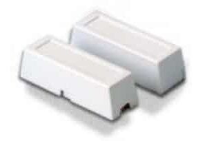
GRI 4701-A Industrial Track Mount Switch Set, 1.75″ 2.75″, SPDT, Open/Closed, Reed Form, 5W
& Free Shipping
- Reversible Probe Assembly
- Left or right installation
- Reversible cable exit
Special Order
Want to be notified when this product is back in stock?
Description
The G.R.I. 4700-A Series Industrial Track Mount Switches are designed to eliminate false alarms from standard floor switches getting damaged by fork lifts and other equipment. The contacts are moved up onto the track and out of the way of equipment.
The 4700-A Series switches are designed to be easy to install and very adjustable. They can attach to a wide range of track sizes and only require tightening one or two screws to install the contacts. It can be installed on either side of the door and the cable exit can be reversed to simplify installation.
An adjustable magnet bracket extends the reach on particularly difficult installations and self drilling screws shorten installations times. Also with a gap of up to 3 inches, doors that wear and get misaligned are not a problem.
INSTALLATION INSTRUCTIONS:
Select a location on the channel that will be out of the way during normal use of the door. The switch can be located anywhere along the channel. This location should also have a matching location on the door when it is in the closed position that the magnet can be attached to.
If necessary reverse the armored cable by removing the screw opposite the cable and moving the probe to the opposite side of the switch. Then just reinstall the screw.
Before assembling the switch, back out the hex head screw until the end is flush with the switch body. Assemble the switch by sliding the hinge plate into the slot on the switch and inserting the L shaped bracket into the other slot on the switch. (XL version: Install the countersink screw and nut through switch body and L shaped bracket. Snug nut up letting L shaped bracket still slide.) (Optional: Install piece of double stick tape on inside of short side of L shaped bracket to prevent movement from track vibration.) Then squeeze the switch assembly around the channel making sure the switch locks into a slot on the L shaped bracket. (XL version: Tighten the nut making sure that the switch stays in the slot on the L shaped bracket.) Then just tighten the hex head screw to firmly attach switch to channel.
The magnet is installed by locating a position on the door that will be out of the way as the door is opened and closed. The magnet should be placed vertically and so that it will stay in range of the switch as the door wears or moves around. There are multiple mounting positions on the magnet bracket in order to make finding the mounting position easier.
Main Features
- Reversible Probe Assembly
- Left or right installation
- Reversible cable exit
- 3 ft. armored cable standard
- Multi position adjustable magnet bracket
- Closed loop or SPDT
- Hinge design for tighter clamping to track
- Up to 3″ gap
- Fits channels from 1.75″ up to 4″
- Self drilling screws included for easy installation
Additional information
| Weight | 1 lbs |
|---|---|
| Brand |


